Documentation about the WinCUPL language can be obtained
here.
As with GAL's what is nice about CPLDs is that changing the circuit on
a board is a trivial task.
Also as with GALs when writing CPLD code you have to be take care to get
active high and active low signals correct. You can either define the pin
signals as active HIGH or active LOW (with a "!" in front of the signal), If you
then have an active LOW in the equations you simply use the name without
the "!". Using a "!" in the equation would be a double negative and flip its
value to HIGH.
Alternatively you can define all pins as HIGH (no "!" anywhere in the pin
definitions part) and then in the equations use a "!" as needed.
The former case actually is more common, though I often use and find the
latter easier to understand.
A Simple CPLD Programming Motherboard.
All the S100Computers that utilize CPLDs do and will contain a "JTAG" socket to
allow in the bus programming with the above simple 6 pin Rockford Programmer. If
there is room I will try in future boards, to also include the more
standard Atmel 10 pin "JTAG-A" socket.
There can sometimes be an issue
with re-programming old CPLD's from other boards in that depending on the last
use of the chip there can be bus direction conflicts from the CPLD pins before the chip is
reprogrammed within the bus. For new chips this is not a problem.
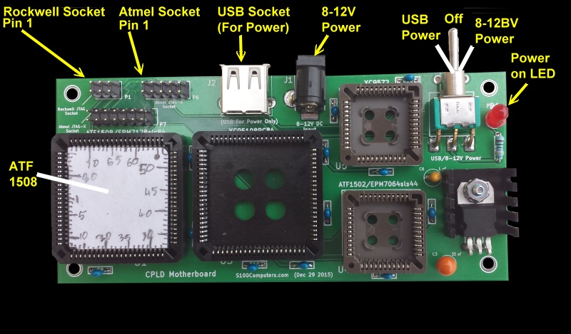
For convenience I have built a small CPLD programming motherboard as shown
here:-
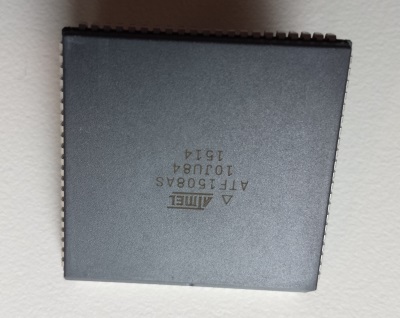
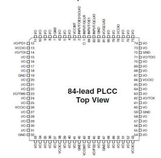
This board will accommodate not only the ATF 1508 CPLD's but also ATF
1502's and 1504's. I believe this also covers the equivalent Altera Max
7000 chips.
There is also a socket for the Altera epm7064slc44 which is probably equivalent
to the ATF 1502 (but different pinouts).
There is a socket for the epm7128slc84-6 and the epm7064slc44 and Xilinx XC9572
also.
Besides the Rockford Programmer you can use the more common Atmel 10 pin
"JTAG-A" socket with for example the
Kanda.com programmer.
Please note, to date, I have only used this board to program ATF 1508's
with the Rockford unit. The rest of the layout is based on suggestions
from others, in particular the great help I got from David Mehaffy (Jedi
Master). The board is quite simple.
It is very important the pin 1 of the programming connector (Rockwell or Atmel)
lines up with pin 1 of the onboard socket of this unit. If not the CPLD
will be damaged during programming.
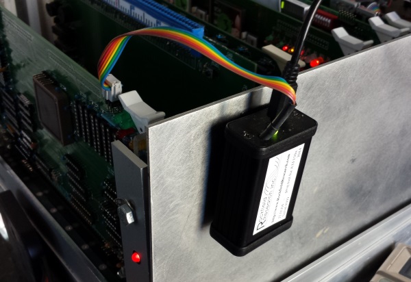
The same is true if you use the JTAG connectors on the S100 board. Here is
a picture of the correct arrangement with the Rockewll connector.
One final point. Removing these PLCC chips from the socket is quite
difficult. You must use a special two pronged chip removal tool. These are quite
common for example Jameco #16766.
BUGs
The WinCUPL program is somewhat "delicate". While it is fast and gets the job
done, it seem to have a few internal glitches. In particular it
seems to be very particular as to the file name path of your
.PLD code file. As best I can tell it has to be
a sub-folder within the \WinCupl folder.
Also it seems sensitive to the overall path character length. In the
latter case it will appear to assemble correctly but the will be no
.JED output file.
I stress again...
WinCUPL and the Atmel fitters are old DOS-era tools, so they often fail silently
or partially when the path is too long or contains awkward Windows-style folder
names. A good safe project path would be something like:
Atmel WinCUPL Windows IDE Interface Download
(Vitasoft, 60008009)
WinCUPL users manual
ATF150x.zip (Rockfield
program to burn 1504's or 1508's)
CPLD Motherboard KICAD
Files
(10/17/2016)
CPLD
Motherboard Gerber Files
(10/17/2016)
CPLD Programming
Board Schematic
CPLD Programming Board Layout
CPLD Motherboard BOM.pdf
(4/5/2018)
(Supplied by Rick Bromagem)
CPLD Motherboard BOM.XLS
(4/5/2018)
(Supplied by Rick Bromagem)
CPLD
Motherboard parts layout.pdf
(4/5/2018)
(Supplied by Rick Bromagem)
This page was last modified
on 06/13/2026