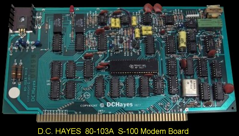
The 80-103A was an S-100 compatible card which when properly installed,
performed the function of interfacing the S-100 computer bus to a tele©
(telephone company) supplied data access arrangement (DAA). The computer,
using Hayes supplied software, controled the activity of the DCA by moving
bytes into data and control registers and by sensing the status of the
interface and accepting data from the receiving register.
The address decode and control signals select the board and register and
determine whether the processor is performing a write or read operation on
the selected register. If it was determined that the current operation was a
write, the Data Out Bus (DOO through D07) was gated to the selected register
and saved in that register. If the decoding logic determines that the
operation was a read, the selected register was gated onto the Date In Bus
(DIO through D17) with the proper timing so that the processor can accept
the data.
Once the processor has setup the connection to be established and the DCA
was ready to transfer data, the software determined whether to transmit or
receive characters on the line. If transmit was chosen, then the status
register was checked to see if the transmit holding register (TRE) was
empty. The character to be sent was then written into the transmit holding
register. After this operation was complete, the transmit register was
checked automatically to see if it was empty. When it was found to be empty,
the transmit holding register was loaded into the transmit register; the
transmit holding register was marked empty allowing the next write.
Following this transfer the transmit register and associated logic sends a
start bit. When the start bit was finished, the least significant bit was
transmitted followed by the succeeding bits of the character.
If parity was set in the control register, the appropriate parity was
generated followed by the indicated number of stop bits. Each of the
transmitted bits passes
through the modulator where the bit was converted into the appropriate
frequency using a digital sine wove generator. The
originate and answer modes use different sets of frequencies allowing the
ability to transmit full duplex (in both directions at the same time).
Each set of frequencies consists of two frequencies with one frequency
corresponding to each state of the line, i.e. "1" or "0". In all modes the
signal was passed through to the telephone line at the OT arid DR pins of
the telco Interface. Normally (except for the self test), the filter
prevents the transmitter signal from feeding back into the receiver and
prevents noise or unwanted signals from interfering with the data reception.
The received signal comes through the telco interface, passes through the
precision filter, and was demodulated by the digital demodulation circuit.
Start and stop bits are checked for framing, then stripped off, and the
character was assembled
in
the
receive register,
and
if
parity
was called for, the parity was checked creating
a parity error if it was incorrect. When the character was completely
assembled, the logic checks to see if the receive holding register was
empty. If it was empty, the data was transferred from the receive register
and the status was set to indicate that the receive holding register was
full (RRF). If the logic was unable to transfer the received character to
the receive holding register because the previous data has not been read by
the processor, then the overflow error flag was set in the status register.
The self test mode was a variation where the filter was switched to the same
set of frequencies as the transmitter so that the receiver gets each
character sent by the transmitter thus checking the modulator and
demodulator and all parts of the circuit except the transformer coupling the
circuit to the line and the connection to the DAA.
Back in the bad old days when Bell controlled all telephone systems it was
against the law to hook up an "unapproved device" to the phone line. You had
to use a Bell System 1001D CBT coupler or Data Access Arrangement (DAA) from
them (for a rip-off monthly fee). The Hayes 80-103A plugged into
this DAA. That was the way things were before the days of deregulation!
The board itself could have its I/O ports (4 in all), located at any
multiple of 4H up to 7FH. It could also be controlled by memory
mapping though this was seldom used. The board could generate
interrupts on ring detect, data ready etc. though the supplied software did
not utilize this feature.
The manual was well written with examples and details of how to use the
board.
The manual for this card can be obtained
here.
Note on Bell 103 Protocol.
Bell 103 - Asynchronous data transmission, full-duplex operation over 2-wire
dialup or leased lines; 300-bps data rate. Ideal for the "low demand" user
who exchanges files infrequently with another PC user or an on-line bulletin
board. Comparable to ITU V.21. This modulation is well suited for bad phone
lines – as the communication guys use to say "103 modems will work on barb
wire".