Introduction Our Dual IDE/CF card board first done back in 2011 has turned out to be a very popular and reliable board. Over 300 of them have gone out world wide over the years. However CF cards are now not often used these days. More common are the smaller SD cards. This board adds an SD card to the basic IDE/CF card circuit.
Instead of the now rare HEX LED displays used on the CF Card Board, I have switched over to the now common OLED displays to show CPM Track/Sector etc. Like our FPGA disk controller boards (e.g. the FPGA_DC Boards) all access to the SD cards is done via a few one byte commands sent to the board. These commands are processed by the ESP32 and send/receive sector data to the S100 bus over two parallel ports. The two ports are completely configurable to any 8 or 16 bit port number with two dip switches. The default ports are status 80H and data 81H. The
original IDE/CF card default ports remain 30H-33H. Both sets of ports can be reset with the three onboard dip switches (8 or 16 bit ports). The following one byte commands control all SD card R/W sector access:-
CMD$INIT$DRIVE_A EQU 80H ;Initilized SD card drive C: CMD$INIT$DRIVE_B EQU 81H ;Initilized SD card drive D: (Not used on this board) CMD$SEL$DRIVE_A EQU 82H ;**** (Re)select an already
Initilized drive C: CMD$SEL$DRIVE_B EQU 83H ;**** (Re)select an already
Initilized drive D: (Not used on this board) CMD$SET$TRK$SEC EQU 84H ;Set new current TRACK+SECTOR on current drive CMD$READ$SECTOR EQU 85H ;**** Read data from the CURRENT sector (on current sector, drive). CMD$WRITE$SECTOR EQU 86H ;**** Write data to the CURRENT sector (on current sector, drive). CMD$FORMAT$SECTOR EQU 87H ;Format the CURRENT sector with E5's. CMD$RESET$ESP32 EQU 88H ;Reset the ESP32 CPU
CMD$INIT$CF$DRIVE$A 0x89 ;Initilized CF card A: (OLED display info only) CMD$INIT$CF$DRIVE$B 0x8A ;Initilized CF Card B: (OLED display info only) CMD$READ$CF$SECTOR 0x8B ;Read data from the CURRENT CF card sector (on current
track, drive). CMD$WRITE$CF$SECTOR 0x8C ;Write data to the CURRENT CF card sector (on current
track, drive). CMD$START$ESP32 0x90 ;Handshake needed to run program after a reset. (Not currently used)
It should be noted that we are accessing the SD card sector directly. There are numerous examples of reading and writing to SD cards using MSDOS file names. However such an arrangement really complicates things for CPM. It would require an MSDOS "disk file" be setup on the SD card and 512 byte sections of that file would be accessed using a file pointer. Instead we directly access the sector using the Arduino ESP32 functions SD.readRAW(sector_buffer, sector) and SD.writeRAW(sector_buffer,sector). Currently the software assumes up to 0FFH CPM like Tracks and 0FFH CPM likeSectors. These are converted into actual SD card sectors.
Note the actual dual CF card circuit is unchanged on this board so CF cards with
CPM for the original Dual IDE/CF cards will run on this board unchanged. It just will not be able to access the SD CPM card C: Two CF card downloadable images are supplied below to run a non-banked version of CPM3 or a banked version. A version to boot from the SD card has not yet been written.
ESP32 Module The ESP32 modules we will use need to have plenty of GPIO pins since we need two parallel ports and status lines to and from the S100 bus. Here are two examples. The first is a common Chinese "generic" version on Amazon. The second is the well known Waveshare company module. On Amazon check for ESP32 S3. The "DevKitC module" is quite common and inexpensive. i case these become rare at a later date the board will also work with the Waveshare EP32.
There are quite a few others on Amazon etc. but it is very important to be sure the same GPIO pins on these modules (which are the same) is exactly the same on any other ESP32 module you use (or else alter the Arduino.ino file, see below). Here are diagrams of the pinouts of the two modules I used here:- Be sure the GND, 5V and 3.3V pins on your module are the same.
Note the actual modules on the board are upside down for convenient access to the USB at the top for programming/monitoring the module. In the case of the dual USB port module the USB port on the LHS is used for programming.
OLED Module The are numerous small OLED displays these days. I use here a 1.54 Inch OLED Module 12864 128x64 SSD1309 LCD Display. It is available from a number of suppliers. I got mine from Amazon. The ESP32 uses an I2C interface using pins GPIO9 and GPIO8. Programming these displays is quite complicated. Fortunately there is an ESP32 Arduino library to interface the units and send ASCII text.
There seems to be a two types where the four connecting pins are GND,VCC,SCL,SDA and VCC,GND,SCL,SDA. There is a jumper on the board (P23) to accommodate the power for both types. Check the voltage on pins P1 and P2 and jumper P25 to match. Only then add the OLED unit.
Note there are also other similar size OLED displays that have more pins and are not I2C driven. They will not work with this board. There are however larger versions of the 4 pin OLED displays. I have had mixed results getting these to display text completely correctly. SD CARD Modules The SD cards themselves are controlled by SD card adaptors. There are two popular types shown here that are well tested on previous S100Computers boards. The interface will be described below.
The Adafruit has a 5V to 3.3V level shifter so it could be run with just a 5V interface. However the SparkFun does not. All its pins must be 3.3V. For safety we will drive both boards using 74LVC245 voltage level shifters.
The rest of the boards components are standard -- available from Jameco, Mouser, Digi-Key etc. For prototype boards I generally use "double swipe" IC sockets. For a critical board like this I prefer to use "Machine Tooled" IC sockets. However they are more expensive and you have to be particularly careful not to bend the actual IC pins. There is a slight complication for the ESP32 module socket. The spacing between the two rows of 22 pins for both units of the above units are slightly different. The Waveshare module pins are about 0.1" closer. So depending on your module use the appropriate board pin holes.
You can either solder the ESP32 module directly to the board or cut to size single row 0.1"" sockets such as the Jameco #2168173 socket. In fact the pin fittings are so tight you can
initially for testing purposes just press the modules into the board. It takes some time to line up the pins. One way is to place
the unsoldered pin headers into the board and add the ESP32 module and then
solder the connector to it. One disadvantage of the connector is it places the ESP32 too high on the board for the next S100 bus board to fit next door. Finally, if you solder the ESP32 to the board, have it as high as possible because you need room to attach the USB connector cable at the top of the board.
Board Construction There is nothing particular special about constructing this board. Use the normal construction process we have in the past. Be careful with LED and electrolytic cap orientations. The longer lead goes into the square hole. Check also the orientation of resistor networks.
The Pololu 5V exist in a few forms. While the older ones (D24V30F5) are still available and uses P3 it seems Pololu is suggesting users use the newer D24V22F5 (5V, 2.5 Amp) units, it has a different pinout, use this one in P2. The ESP32 S3 module supplies enough current to drive all the 3.3V board chips.
Without any chips on the board pop the board into the S100 bus and check you are getting 5V going to each IC socket that uses 5V. Here is what the board should look like at this stage:-
If this is OK install all IC's to the board, including the ESP32_S3 module (in sockets P8 or P10+P12). As mentioned above, there is a second socket P10 to accommodate some ESP32 modules that have a slightly narrower spacing. (P10 + P12).
Note the ESP32-S3 is mounted on the board upside down so the USB port connection is easily available when the board is in the S100 bus.
Jumper K5 1-2 for an 16 bit port address or 2-3 for 8 bit ports. Set the three dip switches as shown here to select ports 80H and 81H for the SD card (SW2 and SW3) and 30H to 33H for the CF
cards (SW 2 and SW1). See the schematic if you need different ports.
The most common OLED displays use P3 4-6 and 1-3. K1 (board reset), is normally is 2-3.
How the Board Works Before going further open the board schematic (see below) and study it to understand how the board works.
In summary:- The dual CF cards circuit is exactly as in the old IDE/CF card circuit. Nothing is changed. See Dual IDE/CF card for more information
In the default configuration for the SD card uses four S100 bus ports are 80H (IN & OUT) for status bits and 81H (IN & OUT) for data ports.
Because the ESP32 CPU is running at 120MHz data transfer and handshaking have to be bullet proof and simple! Whenever the S100 bus writes a byte to port 81H the bus D00-D07 lines are latched into U9. At the same time S100_WRITE_ENABLE clocks the Flip Flop U6A which ends up as a high on the ESP32 GPIO20 pin. The EESP32 continuously looks at GPIP_20. If it is high it realizes S100 bus data is available. After the ESP32 reads the 8 bits on U8 it pulses its GPIO_2 pin low. This resets the U6A Flip Flop and now lowers GPIO20 indicating to the ESP32 the byte of data has been read. This process is done reputedly for all data coming to the ESP32.
Whenever the S100 bus reads a byte send by the ESP32 to port 81H the U15 input lines (GPIO_35-GPIO_42) are held steady with the 8 bits of data. The ESP32 GPIO_1 pin also sets the Flip Flop U6B which goes on to raise bit 7 of status port 80H (DI7) of U14. Once the S100 bus sees this it reads the data from U15 (S100_READ_ENABLE). This also resets the Flip Flop U6B (using U17B). The ESP32 also looks at pin GPIO_21 on U10 which tracks when the data on U15 was read by the S100 bus. Another byte of data from the ESP32 is never sent until the previous byte was read by the S100 bus. This handshaking has to be rock solid because every sector (512 bytes) of data passes back and forth between the SD card and the S100 bus. Because the ESP32 has a clock of up to 240MHz even with the overhead of Arduino code (see below) the data transfer process is very fast. Note no (slowing) resetting bits on the S100 bus side is required. The rest of the board is fairly straightforward, The OLED display uses an I2C interface from the ESP32 (pinsGPIO_8 and GPIO_9). The Arduino ESP32 Code One very nice thing about these ESP32 modules is that the popular Arduino IDE interface can be used to program them. With this board you need to configure the Arduino interface/tools/board to be an ESP32 S3 Module. Hookup USB connection to your computer. You need to also let the Arduino IDE which computer "COM" port is connected to your ESP32. The Arduino code utilizes a few libraries and .h files:- #include "FS.h" #include "SD.h" #include "SPI.h" #include "Wire.h" #include "Adafruit_GFX.h" #include "Adafruit_SSD1306.h" #include "SSD1306Ascii.h" #include "SSD1306AsciiWire.h" #include "fonts\TimesNewRoman16.h" #include "fonts\X11fixed7x14B.h" If your current Arduino IDE does not have them you need to download them from the web. If you are not familiar with using the Arduino IDE and the ESP32 you should first see a few YouTube demos. For example here. Once the code is uploaded to the ESP32 it resides there even when power is turned off. To change the ESP32 code you need to upload a new program via the USB port.
The one tricky part is writing code to read and write to the S100 bus 8 bit parallel ports. (The ESP32 does not have a direct port input). Here is the code:-
char Input_PARALLEL_Port() { char PARALLEL_value; PARALLEL_value = digitalRead(GPIO_NUM_4) + (digitalRead(GPIO_NUM_5) << 1) + (digitalRead(GPIO_NUM_6) << 2) + (digitalRead(GPIO_NUM_7) << 3) + (digitalRead(GPIO_NUM_15) << 4) + (digitalRead(GPIO_NUM_16) << 5) + (digitalRead(GPIO_NUM_17) << 6) + (digitalRead(GPIO_NUM_18) << 7); gpio_set_level(GPIO_NUM_2,HIGH); // pulse U15 LE high gpio_set_level(GPIO_NUM_2,LOW); // return U15 LE low return(PARALLEL_value); } Once setup, the ESP32 sits in a continuous loop waiting for 8 bit commands coming from the S100 bus. They are:-
CMD$INIT$DRIVE_A EQU 80H ;Initilized drive A: CMD$INIT$DRIVE_B EQU 81H ;Initilized drive B: CMD$SEL$DRIVE_A EQU 82H ;**** (Re)select an already initilized drive A: CMD$SEL$DRIVE_B EQU 83H ;**** (Re)select an already
Initilized drive B: CMD$SET$TRK$SEC EQU 84H ;Set new current TRACK+SECTOR on current drive (new) CMD$READ$SECTOR EQU 85H ;**** Read data from the CURRENT sector (on current sector, drive). CMD$WRITE$SECTOR EQU 86H ;**** Write data to the CURRENT sector (on current sector, drive). CMD$FORMAT$SECTOR EQU 87H ;Format the CURRENT sector with E5's. CMD$RESET$ESP32 EQU 88H ;Reset the ESP32 CPU
CMD$INIT$CF$DRIVE$A 0x89 ;Initilized CF card A: (OLED display info only) CMD$INIT$CF$DRIVE$B 0x8A ;Initilized CF Card B: (OLED display info only) CMD$READ$CF$SECTOR 0x8B ;Read data from the CURRENT CF card sector (on current
track, drive). CMD$WRITE$CF$SECTOR 0x8C ;Write data to the CURRENT CF card sector (on current
track, drive). CMD$START$ESP32 0x90 ;Handshake needed to run program after a reset. (Not currently used) Each commandhas a specific format of an initial 33H byte, then a one byte command listed above and for sector R/W the sector number (0-FFFFH). The hardware above clocks each byte back and forth between the S100 bus and the ESP32/SD card. The two byte command with the first byte always being 33H is for safety. You don't want an noise/incorrect byte getting by. I never had this problem here however. S100 Bus Test programs In order to test this board I have written two short Z80 programs that run at 100H in RAM. They are SD_IO.Z80 and SD_CARD.Z80. The ESP32 also needs to be programed. For SD_IO.Z80 the ESP32 Arduino program is ESP32_SD_Boards_IO_Tests.ino For SD_CARD.Z80 the ESP32 Arduino program is ESP32_SD_Boards_Runtime.ino
First lets try the simplest program
SD_IO.Z80. This program is assembled using the Altair PC program seehere. The .COM file is send over to the S100 bus with a program like Tara Termor Absolute Telnet being
received via the MasterZ80 Master monitor "X' menu option
So we load SD_IO.COM (see below), to RAM at 100H with the Master monitor with the Master monitor "X" command. Then type G100, you should see:-
There are only 3 menu options. These test the handshaking signals between the ESP32 and the S100 bus. You must comment in/out the
appropriate section of ESP32_SD_Boards_IO_Tests.ino for each menu test.
gpio_set_level(GPIO_NUM_2,HIGH); // Set U4A LOW will set U6A reset high gpio_set_level(GPIO_NUM_2,LOW); // Set U4A LOW will set U6A reset high ClearErrorLED(); // COMMENT IN/OUT THE TEST REQUIRED while(1) { // data = GetData(); // Get data Test // sprintf(string_buffer,"\r\nGot data (80H) = %x",data); // Serial.println(string_buffer); // data = GetData(); // sprintf(string_buffer,"\r\nGot data (81H) = %x",data); // Serial.println(string_buffer); // data = GetData(); // sprintf(string_buffer,"\r\nGot data (82H) = %x",data); // Serial.println(string_buffer);
// data = GetData(); // Get String Test // sprintf(string_buffer,"\r\n(String test, Got data = %x",data); // Serial.println(string_buffer); // SendString(string_buffer);
You should see the following output on the S100 bus console:-
Do not go further unless the above 3 tests work correctly.
SD_CARD.Z80 Next load the ESP32 resident program from ESP32_SD_Boards_Runtime.ino. This is the "normal" runtime program that always resides within
the ESP32 regardless of the CPM3 version.
Before going to CPM3 we need to test sector reads and writes. Load SD_CARD.COM (see below), to RAM at 100H with the Master monitor (see below), to RAM at 100H with the Master monitor "X" command. Then type G100, you should see:-
This program is
utilized for both this single SD_SD card board and the Dual SD Card Board. We just ignore the second SD card options (B,D) here
(it's for our
Dual SD card board). Make sure you have an SD card in what will be CPM3 Drive C:.
The CPM BIOS (see below) will flag you if an SD card is absent, and will
continue with drives A: & B:, not so for this program.
Upon power up the OLED display should signon like this:-
Start with menu "A" to
initialize the SD card access. The critical tests are "R' and "W" to read or write to an SD card sector. for "R' you should see the following on the OLED display:-
and the actual 512 byte sector contents on the console.
Hitting the space bar will display the next sector. Hit the ESC key to return to the main menu. Note in the default configuration the board assumes a CPM disk of 0FFH CPM tracks with 0FFH sectors/track.
CPM likes to have its directory disk sectors Initilized with E5's. The "F" command will do this. There is no need to format the whole disk, just enough for a disk
dictionary table (e.g, 3 tracks). Here is a sector formatted with the "F" command.
For SD card reading and writing sectors is fast and very reliable. However the OLED display we will see when using CPM3 (See below) does slow things down. For this reason SW5 can turn on or off the OLED display during normal use. The "Reset ESP323" is just the for debugging purposes and is not used in normal use.
There are many SD cards available these days. Since we will be running CPM or MSDOS we only need low capacity cards. I find the 8GB Gladstone cards to be best. However its very important each card is formatted in a PC first with a FAT32 format. An unformatted card will give errors.
Booting with CPM3 (Non-Banked & Banked). First, CPM3 can be booted using
any of the old IDE/CF cards. However Drive C: will not be recognized nor
will the OLED Display show drive/sector info.
This is because the BIOS must send commands to the ESP32.
Likewise the CPM3 versions for this board (see below) will not run on the old
IDE/CF board, They are expecting feedback from an ESP32 module.
A modification to the BIOS to check for the ESP32 could be written but that is
not done here.
A Non-Banked CPM3
System
This is the simplest arrangement and should work with most hardware. The only
requirement being the BIOS Console I/O must be port 0H & 1H. This can be
easily modified (see below).
Our Propeller driven
Console IO Board is normally used.
In order to get people up an running I am supplying a Non-banked "CPM3 Image Disk"
These can be seen
here. It's under CPM3 CF+SD Card Image #12
If you are not familiar with booting up a CPM3 system you need to read that page
and also
here.
Making a Functional CPM3 CF Card. These days one usually writes a CPM3 BIOS
and makes a CPM3.SYS file on a PC using
Peter Schorn's
AltairZ80 Simulator.
The challenge is getting files on to your S100 disk system when you don't yet
have a functional system.
We get around this chicken and the egg problem
by using a complete functional CPM3 "disk image" on a CF card and booting
CPM3 directly in your S100system which has programs to download further files
etc. from your PC. We don't need to dwell how the first S100 bus CF card was made here.
Suffice to say, with such a CF card you immediately have a fully functional CPM3
system from which you can developed more elaborate hardware and software.
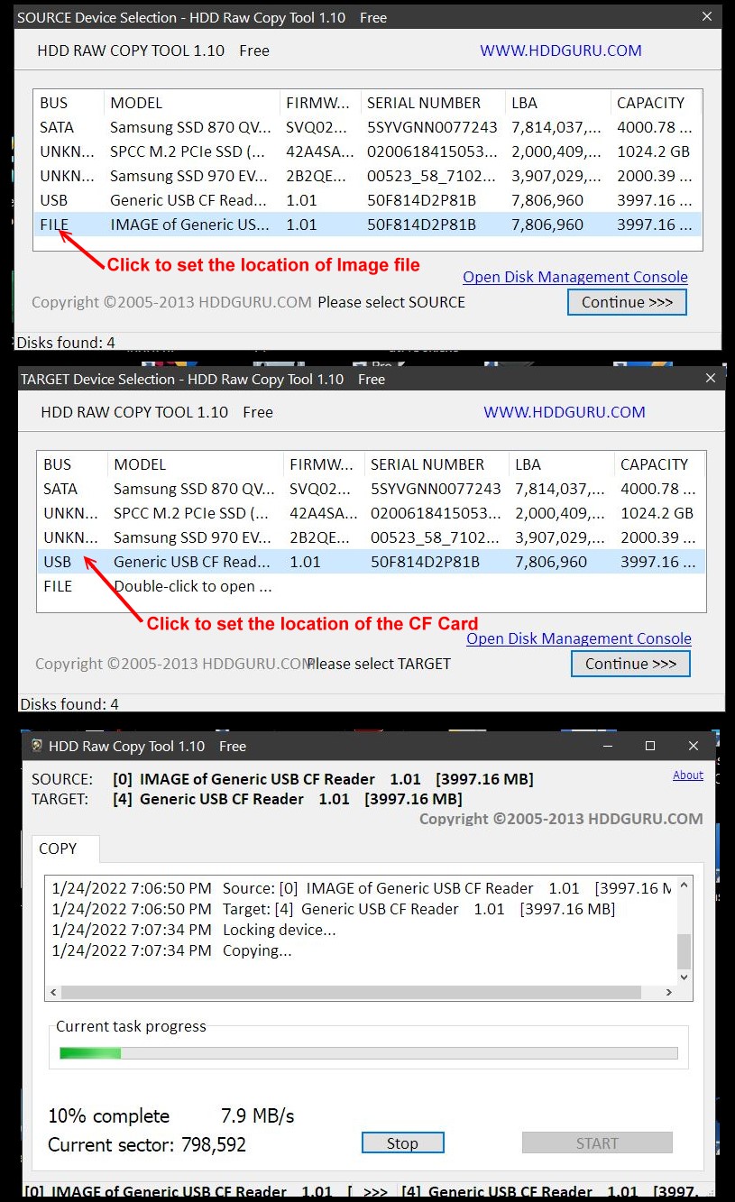
We will use the program called HDD Raw Copy Tool to make
a fully functional CPM3 'disk' from a file that resides on your PC. The
program can be found
here.
It can also be found at the bottom of
this page. There are a number of disk
image files there. Here we need to copy the
CF card image file #12. Because they are actual
sector by sector CF card copies they are quite large (typically 6-7MB).
Typically I use 4GB CF Cards. This is way overkill for CPM3 (but not MSDOS
etc.). I found that HDD Raw Copy Tool
does not copy reliably with older small size CF cards. Likewise the new
high capacity cards caused me some problems. If possible use Kingston or
Verbatim 4GB cards.
Make sure to format a CF card with FAT32 first.
Here is a picture of HHD Raw Copy
being used to unpack the FPGA_DC_CPM_Image.imgc on to a CF card. Actually since our CPM3 disk is only 0FFH tracks,
with 0FFH Sectors/Track maximum, you can probably stop the unpacking process after sector 0FFFFH (65,535). Here is how the "unpacking" dialog looks:-
Be real careful in picking the target drive. This program will esaily overwrite
a valid widnows disk.
Modifying your CPM3 Image. The above Non-Banked CPM CF card image should signon like this:-
You should be able to move files around between disks with no problems. Use PIP +
[V]
Should you wish to enhance your CPM3 image with Floppy disks etc. You will need
to build a new CPM3.SYS file.
This is described in detail
here. I am supplying below the complete folder to build a CPM3 Non-banked
image for this board.
The goal is to make a new CPM3.SYS file. Then after booting your current
CF card CPM3
you can use the supplied PCGET.COM or USBGET.COM program (already on the CF
card) to download the CPM3.SYS file
to your C: drive. The next time you reboot the new system will be active.
Remember however if there is a bug in the CPM3.SYS file your system may hang.
Always have a second CF card with a working image.
Then just PIP the working CPM3.SYS file to the "bad" CF Card and try again.
One final thing to keep in mind. CPM3 needs a bootloader file as well that
resides on the first few sectors of any bootable CF card.
This bootloader can be non-banked or banked (see below). The above image
#12 has this bootloader on the CF card.
However if you use a new CF card (FAT32 formatted) the loader needs to be
placed on the card.
This can be done in a few ways:-
1. Just "burn" the above image #12 to a new card. Then with the card
in your B: drive erase *.*.
The copy all files across including CPM3.SYS.
2. Use the MYIDE.COM program (On the image #12 disk) and copy the first few
tracks of A: to B:
Then erase *.* on the B: drive. Then copy all files A: to B:
across including CPM3.SYS.
3. Use the CPM3 Bootloader HSYSGEN.COM program described
here and on the CF card image #12 disk.
A Banked CPM3 System
This is a bit more complex but the process is the same as for the non-banked
version of CPM3.
Again the only
requirement being the BIOS Console I/O must be port 0H & 1H. This can be
easily modified (see below).
Our Propeller driven
Console IO Board is normally used.
In order to get people up an running I am supplying a Banked "CPM3 Image Disk"
These can be seen
here. It's under CPM3 CF+SD Card Image #13
Again if you are not familiar with booting up a CPM3 system you need to read that page
and also
here.
Here is what the Banked CPM3
signon looks like.
Everything said above for the non-banked version of CPM3 is
also true for the Banked version.
You just have a far larger TPA.
Bugs:- None so far.
A Production S-100 Board. Realizing that a number of people might want to utilize a board like this together with a group of people on the Google Groups S100Computers Forum,
a "group purchases" is now open. I
don't want to put out the board until a dual SD card version of CPM3 for the board is written. Please see herefor more information on older boards.
The links below will contain the most recent schematic of this board. Note, they may change over time and some IC part or pin numbers may not correlate exactly with the text in the article above.
ESP32_Dual_Core_Test.ino Code to program the ESP32 S3 Module
for basic IO tests (5/7/2025) ESP32_2CF+1SD_Board_Runtime.ino
(as .text file) Code to program the ESP32 S3
Runtime code (5/7/2025) SD_IO.Z80 Code to test the board data handshaking on the S100 bus (5/7/2025) SD_Card.Z80 Code to Read/Write SD card sectors from the S100 bus (5/72025) SD _Card _Z80.ZIP Folder Complete Folder of Z80
test files (5/7/2025) Other pages describing my S-100 hardware and software. Please click here to continue...