
| Home | S-100 Boards | History | New Boards | Software | Boards For Sale |
| Forum | Other Web Sites | News | Index |
Cromemco TV Dazzler
This was the board that launched the Cromemco company. It was the first home computer color video board and went on in modified forms over the years to be utilized in specific Cromemco graphic applications such as weather charts for TV stations. It was a two board set. It was first described in Popular Electronics in Feb 1976.
 |
|
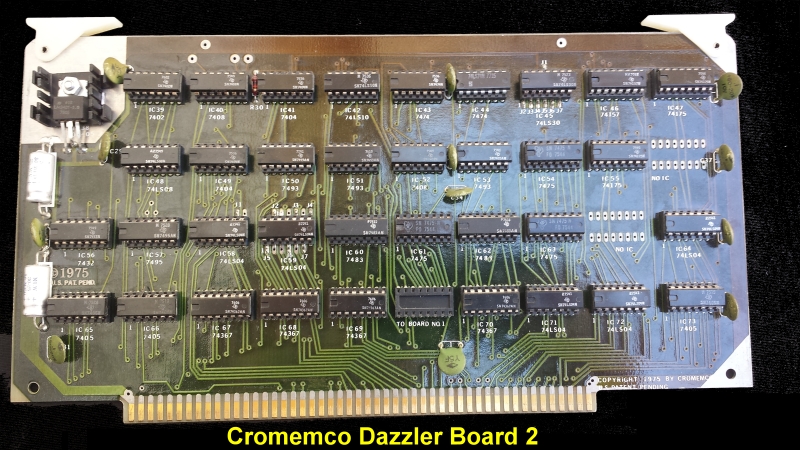 |
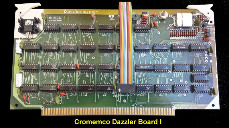
This board set was a marvel at the time (1977). It was designed by Terry Walker at Cromemco. Using only MOS & 7400 IC's the pair of boards that together allowed nice color graphics to be displayed on a home TV screen. Up until then, the only comparable electronics for the hobbyist were ones based on the circuitry described in detail in the pivotal Don Lancaster book the TV Typewriter.
The board was a two board set they were connected by a 16 pin ribbon cable that ran up and over one board and down to the next board behind it. The boards accessed up to 2K of system RAM via DMA putting wait states on the CPU while the info from RAM was picked off. This RAM location could be anywhere on a 1K boundary in the 64K space. Various resolutions of graphics display were possible ranging from 32X32 color pixels up to 64X64 displays. Primitive by today's standards, but a marvel at the time. Ports 0EH and 0FH was hard wired as the control/display format ports. Video output was generated by board 1. Board 2 was used to communicate with the computer CPU.
Video output was composite video which could be sent directly to a composite video input of a TV (if you were lucky at the time to have one with this option) or through the TV antennas via a small RF converter board. They recommended a converter from ATV Research (see below).
HISTORY
The Dazzler came about when Roger Melen of Stanford University saw an article in Popular Electronics magazine, demonstrated the original Altair 8800. After seeing it, he purchased Altair #2 and with his friends Harry Garland and Terry Walker built an add-on video board for the machine. The "TV Dazzler" was originally developed as a display device for the Altair Cyclops version of the Cyclops camera developed by Terry Walker. The history of the development of the Cyclops cameras and the TV Dazzler is given here. This board set, (the Dazzler), was first introduced at the Homebrew Computer Club on November 12, 1975.
Like many early S100 board projects of the time, the Dazzler was originally announced as a self-built kit in Popular Electronics. Sales were so fruitful that Melen and Garland formed the company Cromemco to sell the Dazzler and their other Altair add-ons, selecting a name based on Crothers Memorial Hall, their residence while attending Stanford.
Cromemco quickly branched out into their own line of Z80-based S-100 compatible computers. Over time these became the company's primary products.
Cromemco also sold a package of simple games/graphics for the Dazzler boards. These were supplied on paper tape! or cassette tape or 8" floppy disks (later).The manual for the board can be obtained here.
The manual for the computer games that ran with the board can be obtained here.
Information about adapting the board to work with a TV RF signal can be obtained here.
Here is an early (1976), Popular Electronics Cover Article for the board
The Cromemco SDI Video Board
In 1979 Cromemco replaced the original Dazzler with the “Super Dazzler”. The Super Dazzler Interface (SDI) had a 756 x 484 pixel resolution with the capability to display up to 4096 colors. Its onboard two-port memory was used for image storage for higher performance. Unlike the original Dazzler which had a composite video output signal, the SDI board used separate RGB component video outputs for higher resolution. The SDI also had the ability to be synchronized to other video equipment.
Interestingly, the Cromemco SDI board became the systems of choice for television broadcast applications. They were also widely used by the United States Air Force in Mission Support Systems.
The manual for the SDI board can be found here.
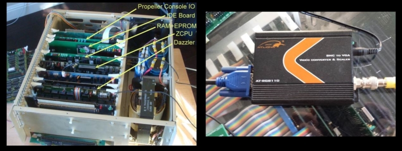
In December 2013, I decided to fire up an old Dazzler board I had. I placed it in a CompuPro box (see picture below). This took some effort to get the system working. First, unlike most later S-100 boards, this early board would only display graphics with the corresponding Cromemco CPU board the "ZCPU" board. While the Dazzler would not interfere with other S-100 bus CPU boards, the image displayed on the screen was always a blank white color. Furthermore, a number of older S-100 bus RAM cards would not work (display graphics) with the Dazzler board. Surprisingly this included the CompuPro RAM 16 and RAM 21 boards. Fortunately both the Cromemco "ZCPU" and our own RAM+PROM N8VEM/S100 Computers worked fine with the board. The Cromemco ZCPU board requires an external EPROM which was supplied on the RAM+EPROM board. However the ZCPU board is only capable of addressing up to 64K of RAM so I had to utilize a non-banked CPM3 system on a CF card for our IDE board (with a 44K TPA).
I have not looked into why the Dazzler DMA does not work with a number of other (non Cromemco) CPU boards. It's not absolute however, I do know the Dazzler worked with the SD Systems Z80 CPU board - my original S100 bus CPU board!. Perhaps others could be added to the list. BTW, it is this type of issue that lead to the standardization of the S-100 bus signals in the form of the IEEE-696 standard - used if almost all later S-100 boards.
I actually no longer own a classical CRT TV set. I converted the Dazzlers Comp. Video output signal to a VGA LCD display utilizing a "converter box" . A number of these are available these days. I really like the Atlon (AT-RGB-110) shown in the picture below.
 |
The next challenge was software. Most Dazzler programs were written before CPM became common and so, as written, are really not compatible, often residing in RAM at 0H. The most famous Dazzler program was "KScope". This simple program (less than 200H byte of RAM), delivers a spectacular display of colors/patterns continuously. I rewrote the program to load with CPM and run in the above system. Here is a brief video of the pattern seen:-
The S-100 Bus Dazzler Board in Action:-
The two short (amateur) videos below shows the KScope graphics action (left) and another Cromemco demo video (below).
To play this video click on the arrow within the window.
To play this video click on the arrow within the window.
The KSCOPE program itself can be obtained here
Other games software can be found here and here
Notes
David Roberts analyzed the issue of the Cromemco Dazzler not working with some early S100 bus RAM boards.
He writes...
I tracked this DMA problem down to memory boards that utilise a latch on the S-100 address bus. The Dazzler DMA cycle is quite crude. Basically, the desired address is output to the S-100 bus, and the control signals forced to a static memory read cycle.
The address bus is cycled around
the desired addresses by the Dazzler, but no S-100 control lines are
adjusted in the process.
I have checked a number of other (Cromemco) static RAM cards that work and they use address latches as well. The difference appears to be that the S-100 clock is also used as part of the logic driving the address latch strobe input (i.e. I suspect the address latches are strobed based upon the clock signal even if a static memory read cycle is 'jammed' onto the S-100 bus).
Other Cromemco 100 Boards
ZPU SBC 4KRAM 16K RAM 64KZ RAM 64KZ-II RAM 256KRAM 8KBytesaver Bytesaver-II
16KPROM 32K Bytesaver 4FDC 16FDC 64FDC WDI WDI-II STDC DPU
4PIO 8PIO TU-ART D+7A I/O Dazzler PRI GPIB Board XMU XXU Other Boards
This page was last modified on 04/07/2024